


The O-ring was initially used in hydraulic systems to provide sealing preference and address the leakage problem. After designing the hydraulic cylinder, a sealing test for the hydraulic cylinder was required to ensure that the system was safe without leakage. This study compares the contact pressure of seals using two different designs: a key design in the V-V direction with a boom single-sided diagonal bolted installation method, and an initial key design from the company in the H-H mounting direction with the fully bolted boom installation method. A comparison was conducted through simulations, and the effectiveness of both designs was verified using FEA.
Test modelling and material
A section radius of 5.15 mm and the radius of the O-ring seal were designed to hold a good seal between the hydraulic cylinders. The seal exhibited an interference of 0.3 mm with the cylindrical part, as shown in Fig. 14.

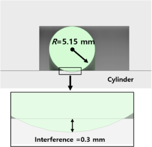
Dimensions of test modelling of the O-ring seals.
The mechanical properties of the seal made from a fluoroelastomer (FKM rubber) were determined using Yeoh’s hyperplastic model equations. This mathematical model is a well-known method in materials science for characterising the nonlinear elastic behaviour of elastomers. In this study, the Yeoh third-order modelling was used as described below.
$$\:W={C}_{10}\left({I}_{1}^{{\prime\:}}-3\right)+{{C}_{20}\left({I}_{1}^{{\prime\:}}-3\right)}^{2}+{{C}_{30}\left({I}_{1}^{{\prime\:}}-3\right)}^{3}$$
where \(\:{C}_{10}\), \(\:{C}_{20}\) and \(\:{C}_{30}\) are the hyperplastic material parameters, \(\:{I}_{1}^{{\prime\:}}\) is the first principal invariant, and \(\:W\) is the strain energy density function.
The hyperplastic material parameters (\(\:{C}_{10}\), \(\:{C}_{20}\)and \(\:{C}_{30}\)) were determined through various experiments, including uniaxial tensile, planar shear, and biaxial tensile tests. Table 7 presents the hyperplastic material parameters (\(\:{C}_{10}\), \(\:{C}_{20}\)and \(\:{C}_{30}\)) of both the unaged and aged FKM17. In this study, only the unaged FKM was used, and the hyperplastic material parameters (\(\:{C}_{10}\), \(\:{C}_{20}\), and \(\:{C}_{30}\)) given by \(\:50\)MPa,\(\:\:-66.43\)MPa, and \(\:88.96\) MPa, respectively, were input into the ANSYS program to fit the stress–strain curve of the FKM, as shown in Fig. 15. When the stress–strain curve is fitted, the nonlinear elastic behaviour of the FKM can be simulated using the ANSYS program.
Sealing tests were performed in two cases, which defined the initial design (thickness 6 mm with single-sided diagonal bolted and horizontal mounting method) and the reduced deflection plans suggested in this paper as the best design (thickness 6 mm with single-sided diagonal bolted and vertical mounting method). An elastomeric seal is considered effective in preventing leakage problems if the working pressure does not exceed the contact pressure at the macroscale18,19.

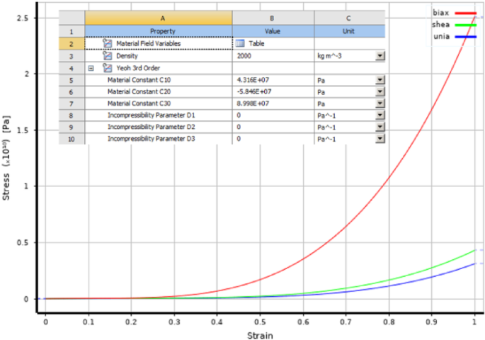
Stress–strain curve of FKM fitting by ANSYS program.
Influence of Deflection on sealing performance
When the hydraulic cylinder reaches its maximum extension position, the large deflection with bending behaviour leads to two contact features between the upper and lower parts of the cylinder surface. When the pressure pushes the seal at the upper groove, the seal at upper groove has more “compression”, implying that more contact pressure is produced at the contact point to provide the fluid leakage. Conversely, the seal at the lower groove has more “tension”, which leads to contact pressure produced at the contact point, contributing to the leakage problem in their region, as depicted in Fig. 16. Points A and D and points B and C indicate the contact points of the upper and lower cap grooves with a seal, respectively.

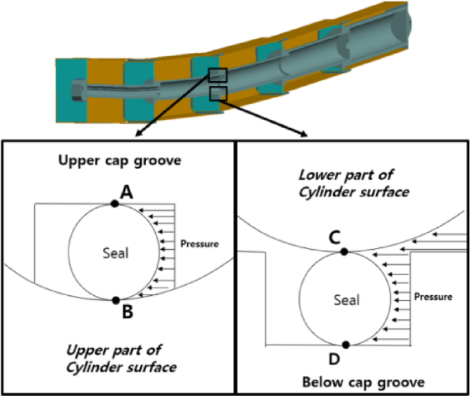
Different sealing states of the up and down location of the groove based on the bending behaviour.
Discussion and result
The sealing test results of the field’s five-stage hydraulic cylinder design, which uses a boom fully bolted installation method in the H-H mounting direction with a deflection of 192.9 mm, revealed that contact pressure values were 16.45 MPa and 17.2 MPa at A and B contact points, and 13.3 MPa and 12.68 MPa at C and D contact points, respectively. Leakage occurred at contact points C and D at pressures lower than the working pressure (13.7 MPa), indicating leakage in the cylinder system as shown in Fig. 17.

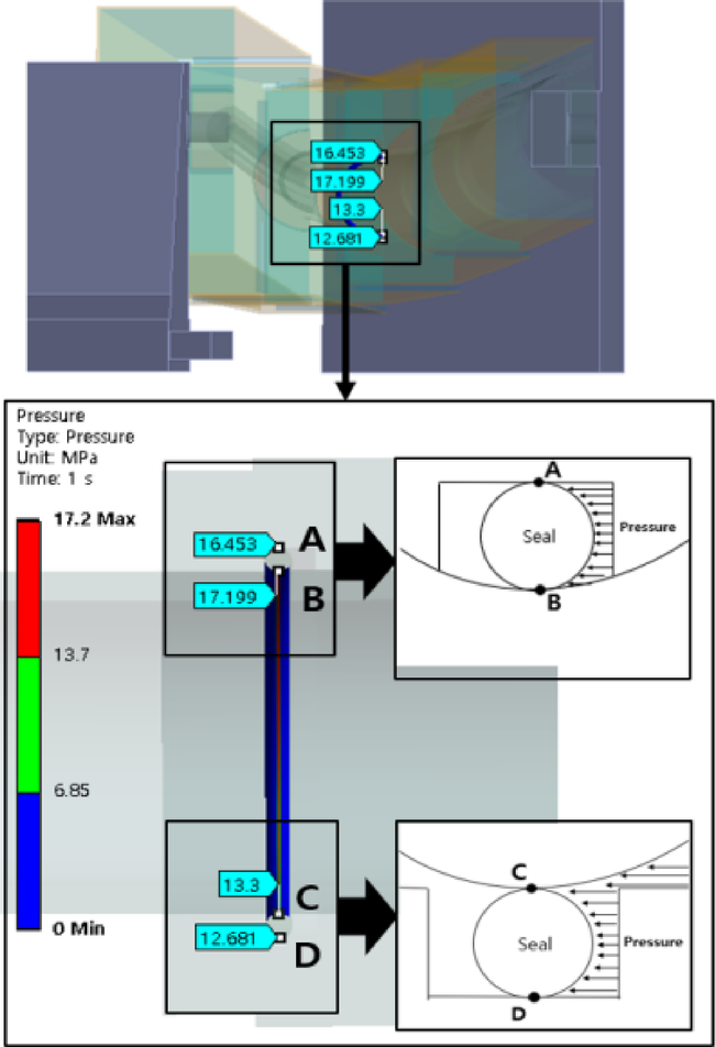
Result of the initial design of the five-stage hydraulic (Deflection: 192.9 mm).
The sealing test results of a five-stage hydraulic cylinder, using the single-sided diagonal-bolt boom installation in the V-V mounting direction, with a deflection of 29.7 mm showed that the contact pressure values were 15.75 MPa and 16.7 MPa at A and B contact points, and 14 MPa and 14.06 MPa at C and D contact points, respectively. No leakage was observed in the cylinder system, as shown in Fig. 18.

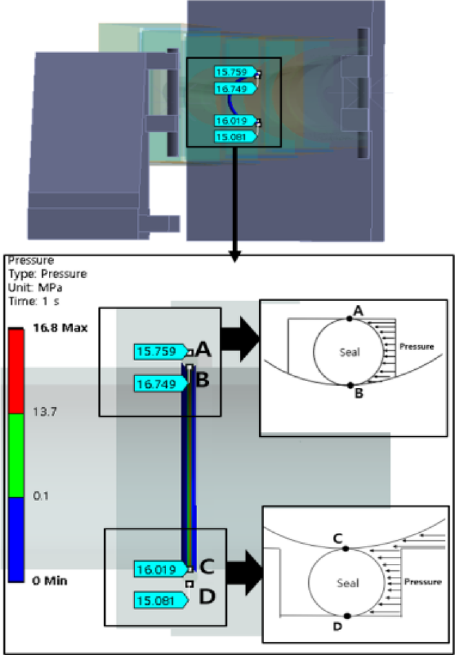
Sealing result of the best design of the five-stage hydraulic (deflection: 29.7 mm).
The contact pressure results are listed in Table 8. These results confirm that deflection affects the leakage of the hydraulic cylinder.
Design of U-lip seals for the hydraulic cylinder
O-rings, rectangular rings, and U-seals are commonly utilised sealing components in hydraulic systems20. Research has shown that under high contact pressure and high rod speed conditions, O-rings used as reciprocating seals in five-stage hydraulic cylinders are prone to cracking, extrusion, wear, and distortion21, ultimately leading to cylinder leakage22, and also the frictional force is twice compared with U-lip seal at same size23 Additionally, high contact pressure accelerates the wear of the seals. Therefore, to reduce wear and cracking while providing reliable sealing performance, this study conducted detailed tests on these three different shapes of seals. The materials used included fluorocarbon rubber (FKM) and hydrogenated nitrile butadiene rubber (HNBR)24, with all tests, carried out under the same working conditions and dimensions (10.3 mm) with 0.3 mm interference to ensure the accuracy and comparability of the experimental results. The test modelling is shown in Fig. 19.

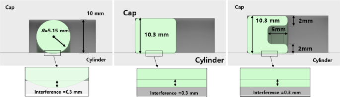
Dimensions of test models for three kinds of seals.
The results for the maximum contact forces of O-rings, rectangular rings, and U-seals made from two different materials, FKM and HNBR, are displayed in Fig. 20. For FKM material, the maximum contact forces are 17.3 MPa for O-rings, 14.4 MPa for rectangular rings, and 13.6 MPa for U-seals; for HNBR material, the corresponding forces are 0.469 MPa, 0.387 MPa, and 0.374 MPa respectively. The study reveals that U-seals exhibit the lowest contact pressure of all tested seals irrespective of the material used. This finding confirms that U-seals experience the least sliding wear under identical operating conditions, significantly extending their service lifespan. Additionally, the study assessed the ageing performance of seals made from FKM under cyclic pressure and temperature variations and compared the performance differences among the three different shapes of seals. Detailed data on the aged FKM material are shown in Table 7. These results provide crucial guidance for optimising seal design and enhancing the reliability and efficiency of systems.

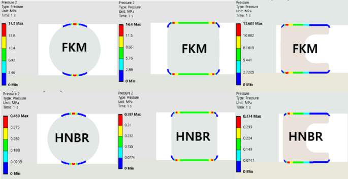
Contact pressure results of O-rings, rectangular rings, and U-seals made from two materials.
The contact pressure results from Unaged and aged FKM materials are shown in the Fig. 21. For O-rings, rectangular rings, and U-seals made from FKM material, the maximum contact pressures decreased from 17.3 MPa, 14.4 MPa, and 13.6 MPa to 14.9 MPa, 12.4 MPa, and 11.74 MPa, respectively, before and after aging. Specifically, the contact pressure for O-rings was reduced by 2.4 MPa, for rectangular rings by 2 MPa, and for U-seals by 1.89 MPa. These results indicate that despite using the same material, U-seals are least affected by aging among all tested seals, showing minimal impact on their sealing performance compared to other types of seals. This finding suggests that using U-seals in future applications may help reduce leakage problems caused by material aging, thereby enhancing the overall reliability and sealing performance of the system. This is particularly important for designing hydraulic systems with long service lives and high reliability.
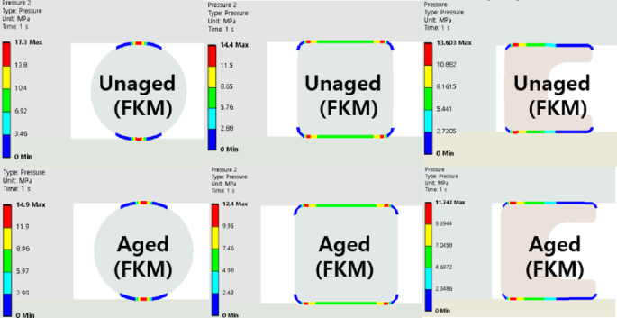
Contact pressure results of O-rings, rectangular rings, and U-seals made from unaged and aged FKM materials.
To optimise for reduced contact pressure in the U-lip seal, Fig. 22 illustrates the key parameters: ‘a’ represents the thickness of the seal lip, while ‘b’ denotes the length of the seal lip. The thickness parameter ‘a’ was varied between 1.5 to 3 mm, and the length parameter ‘b’ was adjusted between 3 and 7 mm. This range was strategically chosen to explore the effects of these dimensions on the seal’s performance.

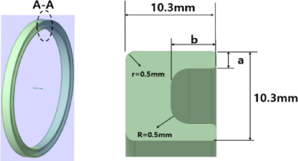
Dimensions of optimise model of U seals.
The contact pressure results of the U-lip seal are shown in Fig. 23. All results indicate that increasing the parameter ‘b’ leads to reduced contact pressure. When ‘a’ is set at 1.5 mm, the contact points A to D exhibit lower pressures compared to other cases; however, leakage occurs when ‘a’ exceeds 5 mm. The optimal configuration in this scenario is observed by 1.5 mm for ‘a’ at and 5 mm for ‘b’. For selections of ‘a’ at 2, 2.5 and 3 mm, the contact pressure is higher than that at 1.5 mm, respectively, leading to accelerated seal wear.

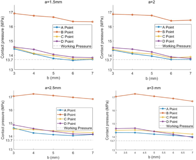
Contact pressure results of U seals.
The contact pressure tests of the U-lip seal revealed that the best performance observed at a = 1.5 mm and b = 5 mm showed two contact circular regions exceeded. Circular contact region 1 (B to C) had pressures ranging from 16.7 to 14 MPa, whereas circular contact region 2 (A to D) had pressures ranging from 13.75 to 14.06 MPa. All circular contact regions exceeded the working pressure of 13.7 MPa, as shown in Fig. 24.

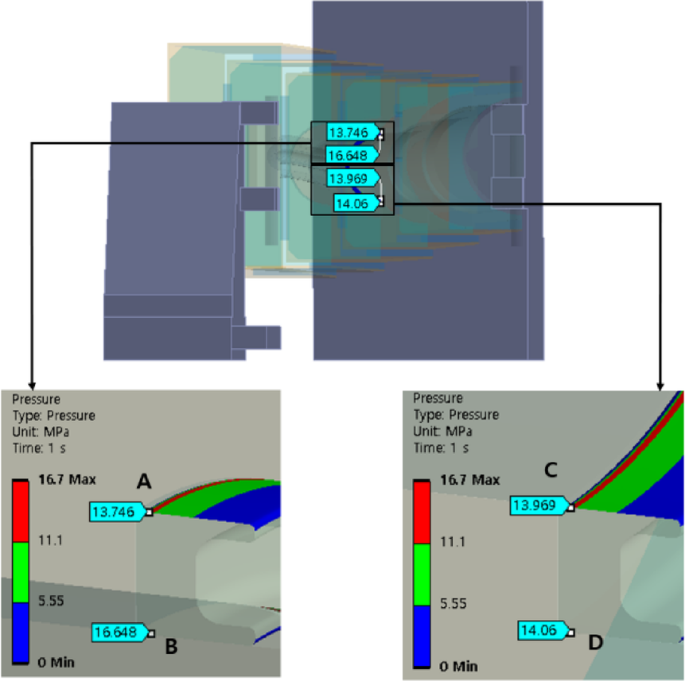
Sealing result of the U-lip seal.
In this study, a U-lip seal with ‘a’ and ‘b’ as 1.5 and 5 mm, respectively, was selected for further tests. Compared with the above-tested O-ring, the U-lip seal exhibited the same interference of 0.3 mm, and its dimensions were 10.3 mm in length and width, as shown in Fig. 25. This design aimed to minimise the excited contact pressure at the contact points, thereby reducing unnecessary wear on the cylindrical components.

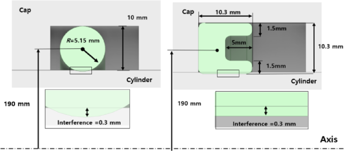
Comparison of tested models of the O-ring and U seals.
Table 9 shows the result of tested contact pressure comparing the O-ring and U-seal, all the contact pressure points (A, B, C, and D) of the U-seal were lower than those of the O-ring seal and the average contact pressure decreased by 8,02%, indicating that the U-lip seal experienced less wear than the O-ring seal. Therefore, a U-lip seal is recommended for use in hydraulic cylinders owing to its lower wear.
This study conducted simulation tests on the seal states at different positions under the maximum working distance of an extended hydraulic cylinder, supplementing factors of the hydraulic cylinder under deflection states that were not addressed in previous 2D simulations25,26,27, especially for multiple-stage hydraulic cylinder for structural safety and sealing analysis. Furthermore, the study analyses the differences in contact pressures produced by different seals at various positions under large deflection states and found through FEA simulation comparison that U-seals are more suitable for hydraulic cylinder applications.
link