


According to ISO 14040 (2006)31 and ISO 14,044 (2006)32, there are four steps to LCA. These are the goal and scope definitions by ISO 140433, boundary study, life cycle inventory, and interpretation of the results. These steps were applied to evaluate the LCA of the concrete in the two buildings. The decrease in concrete strength from the addition of water to the ready-mix concrete was studied to determine pollution emissions and energy consumption.
In this study, the strength of the concrete during the design of the building and the implementation of the desired strength for concrete in terms of structural resistance and environmental pollutants were investigated and compared. The results of LCA from cradle-to-gate to produce concrete were extracted using SimaPro 9.1.1 (2021). The outcome of the damage potential (human health, ecosystem quality, and resources), pollution assessment (global warming, acidification, and eutrophication), and the construction energy were computed using IMPACT 2002+, CML-IA, and Cumulative Energy Demand (CED), respectively. CED computed the embodied energy of all concrete material.
Because Iran does not have a database, a European database which is like the present study was used here. A considerable number of Iranian studies have used a European database. The lack of a database in Iran is one of the limitations of the present study.
Goal and scope (ISO 14041, 1998)
The purpose of this study was to analyze the amount of energy consumption and the environmental LCA of two concrete buildings. Figure 1 shows the LCA system boundary of concrete construction and concrete waste was ignored. A functional unit of 1 kg was considered for all materials (cement, gravel, sand, and water) to ensure a standardized comparison. The LCA was performed as a cradle-to-gate method with a process approach where the range from raw material extraction to the end of the factory production stage and building construction was limited and did not include the use and disposal stage.

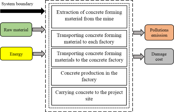
System boundary of the study.
Inventory analysis (ISO 14042, 2000)
A life-cycle inventory (LCI) was compiled using the Ecoinvent 3 database in SimaPro. Ecoinvent3 is a valid and one of the most complete databases available for processing LCA34. SimaPro 9.1.1 is a professional tool for collecting, analyzing, and monitoring the environmental performance of products and services. Using this software, a complex life cycle can be easily modeled and analyzed systematically and transparently in compliance with ISO14040 standards.
Using the features of SimaPro, the user can make positive changes in the life cycle of products. This software is used by industry, consultants, and research institutes by more than one thousand users in 80 countries. It is the most successful LCA software in the world35,36,37. The ISO 14040 standard has been considered for integrated LCA of products, processes, and services.
All necessary data was collected to assess the LCA of concrete buildings having different strengths using information available from the literature review. Also, we present the quantities of materials used to make one cubic meter of concrete, as outlined by the National Standards Organization of Iran. Based on extensive laboratory studies and research conducted in 2007, this organization developed a concrete mixing plan, which has since been made available to industry professionals. We used SimaPro 9.1.1 (2021) and the Ecoinvent database to model the processes of raw material extraction, material production, and internal transportation. Figure 2 shows the plan and elevation for the four-story building on the Ground floor. The total volume of concrete included the foundation, columns, beams, roofs, and stairs. The total amount of concrete in the building was 284.5 m3. This architectural plan was obtained from a consulting engineering design office in Shahr-e-Quds, with the permission of the property owner. We have meticulously measured and documented it, and this project was successfully executed in Shahr-e-Quds, Tehran.

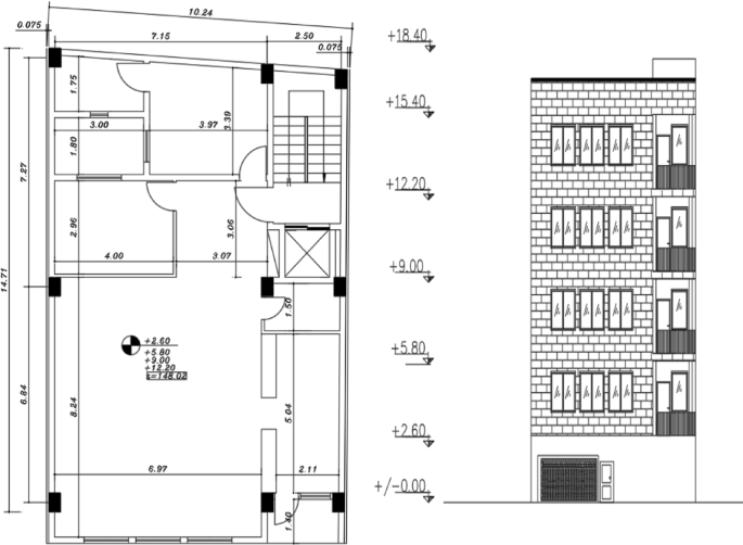
Typical plan and elevation of the building (Units: Meters).
A concrete mix design is the process of determining the ratio of concrete components such that it becomes as cost-effective as possible and meets the physical, mechanical, and durability requirements. The concrete materials used for the mix design should be the same as those used in the project. The Iranian national method of concrete mix design was developed after extensive laboratory studies and research in 2007 and was provided to industry experts. The simplicity of this method and the low incidence of error in making the laboratory mixtures stems from its compliance with the specifications and properties of materials in Iran and is an advantage of this method. The mix design considered for the concrete in the current study was the method instituted by the Road, Housing, and Urban Development Research Center38.
In concrete building construction in Tehran, the strength of the concrete produced in batching plants according to the design specifications decreases from 25 MPa (C25) at the plant to 20 MPa (C20) at the site of consumption. The most important reason for this is delays caused by heavy traffic during transport from the plant to the construction site. Truck drivers add water to the mixing concrete, which increases the water-to-cement ratio and decreases its compressive strength. Calculations have shown that the amount of water added along the route and at the construction site increases the water-to-cement ratio from 0.45 to 0.66. This is the basis of the analysis of this study. All the steps of the mixing process of the batches of concrete for the two buildings were similar and differed only in the amount of water added (Table 1).
Life-cycle assessment (ISO 14043, 2000)
Two identical four-story concrete buildings that were constructed with the same materials except that their concrete strengths differed were investigated. We investigated the effect of the decreased strength of the concrete in one building on the energy consumption, environmental impact (EI), and lateral bearing capacity of the structure.
ELCA of the concrete buildings from cradle-to-gate was performed and analyzed for global warming potential, acidification, and eutrophication using the CML-IA baseline V3.06/EU25 method and the results were compared with those of the BEES + V4.08 method. The effects on human health, ecosystem quality, and resource conservation were analyzed using the IMPACT 2002 + V2.15 method and its results were compared with those from the ReCiPe 2016 Endpoint (E) V1.04 method. The amount of embodied energy consumed was computed using the CED v.1.11 method.
In ELCA, two main approaches are used to classify and characterize environmental impacts: The first is the stop problem-oriented approach, which is modeling before the end of the work and relating the results of list analysis to the middle group. The second is the pathological approach in which the group of effects is related to the last stage of the path of effects and is one of the method’s endpoints39. The basis of the CML-IA baseline V3.06 / EU25 and BEES + V4.08 is the midpoint. The bases of IMPACT 2002 + V2.15 and ReCiPe 2016 Endpoint (E) V1.04 are the midpoint and endpoint.
Our goal was only to compare two types of concrete including C20 and C25, in fact, all the characteristics of the two types of concrete in terms of the amount of cement, the amount of sand, and coarse aggregate were the same, and only adding more water to concrete C25 reduces its strength to C20. Our objective was only to find the effect of adding water to C25 concrete during transportation to the workplace due to traffic, and what effects it will have on the environmental life cycle. Therefore, the purpose of installation, molding, and implementing reinforcement in concrete was not our aim, and the volume of concrete waste was also ignored. According to the database information available in the Simapro software, when using concrete, the transportation of materials and raw materials from the mine to the factory is considered in the information in the software, and there is no need to add the transportation of materials from the mine to the factory again. Because this will cause an error. According to the conditions of different countries, different vehicles are considered in the software. For example, sea, rail, or road transport is considered according to location. In this study, because there is no Iranian database, we tried to choose the concrete closest to the conditions in the study to have the least amount of error in the environmental assessment. We did not consider the transportation distances from the mine to the factory separately because we should have entered the other concrete components in more detail. Due to the limitation in obtaining information on the emissions of each of the concrete components, the calculation error increased.
The transportation of materials distanced from the concrete batching plant to the workplace assumed 30 km as an average distance from the center of Tehran, and transportation from factory to workplace and energy input was computed. Again, the aim was to find the effect of increasing water in concrete on environmental parameters such as global warming, acidification, and eutrophication; therefore, we selected the cradle-to-the-gate process in this research. Table 2 indicates the life cycle inventory and input data to Simapro software for ELCA of one cubic meter of concrete.
Iran does not have a database to assess the environmental life cycle, and the closest adaptation of the data of this work was to Ecoinvent, and Ecoinvent340 was used. Other researchers such as Asadollahfardi et al.19, andAsadollahfardi et al.41, also used this database. We added inventory data (Table 2), and material transportation and amount of energy were also computed.
The transportation of materials from the concrete batching plant to the workplace was considered 30 km. Again, the aim was to find the effect of increasing water in concrete on environmental parameters such as global warming, acidification, and eutrophication (midpoints), and left of midpoints parameters computations were added to supplementary files including (Tables S1); we selected the cradle-to-the-gate process in this research because concrete operation and disposal was not my aim.
Figure 3 indicates the flow diagram of the stages of the environmental LCA and embodied energy. First, the goal of the study was defined. Then, the boundary of the study was determined. Next, the amounts of material used for C20 and C25 concrete were computed (Inventory study). After that, inventory results were used as input to IMPACT 2002+, CML-IA, and Cumulative Energy Demand (CED) of SimaPro software to compute the damage potential (human health, ecosystem quality, resources), and pollution impact (global warming, acidification, and eutrophication). Finally, the results are interpreted.

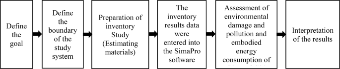
A flow diagram of the stages of the environmental life cycle assessment of the study.
In this article, we calculate the effective percentage of each constituent material in concrete using various methods and present a comparative analysis. Rather than directly comparing the output figures from SimaPro, which would be an inaccurate approach—we focus on separately analyzing the effective percentages of each material.
To facilitate comparisons across different damage impact assessments, we calculated the Human Health Damage Assessment results for C20 concrete and expressed them in percentage terms. We conducted a similar assessment for C25 concrete. As the only difference between these two concrete types is the water content, we compared the percentage of water in each mixture to determine how much more one formulation may contribute to environmental damage than the other. This comparative approach was applied to all damage categories, including ecosystem quality and resource depletion. Since the other materials in both concrete types are identical, the results across these assessments remain consistent.
Structural analysis
In the non-linear static analysis method, the structure is designed for a change in the target location. In this method, by applying a specific force at the center of mass of the roof, the building moves gradually to equal the change in target location and the forces created in the members are calculated. Therefore, the location of the target changes and the force can be obtained. In this basic method, displacement is assumed upon entering the non-linear region and these deformations determine the behavior of the structure. Upon entering the non-linear region, i.e. after the member yields, the deformations will be large with a small increase in force.
The structure model initially was defined in ETABS 2018 (version 18.0.2), and then the materials of the structure, including the concrete and rebar used in the beams, columns, and the sections of the beams, columns, and roofs were defined and assigned according to the building plan. Lastly, the dead and live loads were applied to the structure, and other relevant settings were made. In ETABS, the buildings with 25- and 20-MPa concrete were analyzed separately. A target displacement of 0.251 m was obtained according to the Iranian Code of Practice for Seismic Resistant Design Buildings38.
As shown in Fig. 4, the structure model initially was defined in ETABS 2018 (version 18.0.2) for earthquake assessment, and then the materials of the structure, including the concrete and rebar used in the beams, columns, and the sections of the beams, columns, and roofs were defined and assigned according to the building plan. Lastly, the dead and live loads were applied to the structure, and other relevant settings were made. In ETABS, the buildings with 25 MPa and 20 MPa concrete were pushover analyzed separately. Finally, two structures were evaluated for lateral bearing capacity, displacement, period, and frequency.

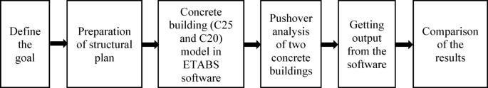
A flow diagram of the stages of the lateral bearing capacity of two concrete buildings.
First, the link between LCA and structural analysis is that we analyzed the LCA and earthquake analysis of concrete with the same concrete characteristics with different strengths including 20 MPa and 25 MPa. Second, we were required to find the relationship between the results of the LCA and earthquake analysis for two types of concrete, which the difference is only in the water-to-cement ratio, and it caused the difference in their strength.
The buildings under study are residential and designed according to Iranian standards, typically with an expected lifespan of 50 years. With proper maintenance and in the absence of significant incidents, a concrete structure is unlikely to encounter key issues during this period. However, various factors—such as changes in regulations, shifts in lifestyle and consumer preferences, fluctuations in land and building economics, and the deterioration of facilities—often prevent residential buildings from exceeding a 50-year lifespan.
In terms of seismic design, it is important to note that for a building expected to last 50 years, the design assumes a ten percent probability that an earthquake will occur during its lifespan. Consequently, the building is engineered to withstand earthquakes with a return period of 475 years.
Limitations of the present study
-
Because Iran does not have a database, a European database that nearly matches the present study was used. The lack of a database in Iran is one of the limitations of the present research in the field of environmental life cycle assessment.
-
Collecting available data is one of the other limitations of the research because companies and organizations do not cooperate properly.
link