
Seismic retrofit of high-rise buildings using buckling-restrained braces: design methodology and performance evaluation

Due to the fact that renovation and strengthening are different from traditional new building designs, the design process is relatively complex, as shown below:
-
(1)
Establish a model based on the original and renovated building drawings;
-
(2)
Analyze the renovated model;
-
(3)
Compare different strengthening schemes;
-
(4)
Compare the calculation results of the model established according to the strengthening plan with the original structural reinforcement bar, and use different methods for strengthening;
-
(5)
Input the original reinforcement bar and reinforcement methods into the model for review of bearing capacity and overall indicators.
The process of this strengthening design is shown in Fig. 2.
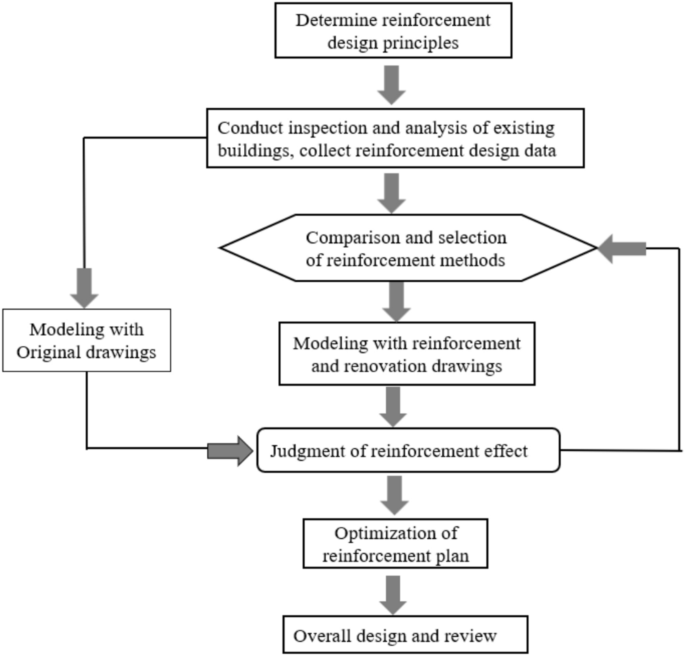
Strengthening design flow chart.
Analysis of structural defects
Analyze the repaired model using the YJK software and find the following key issues:
-
(1)
The overall structural story drift ratio is greater than 1/800, and the displacement ratio exceeds 1.4.
-
(2)
Insufficient bearing capacity of beams and columns in the original structure.
-
(3)
The axial compression ratio of some frame columns on the bottom floor does not meet the requirements.
Scheme comparison for structural strengthening
In response to the above issues, compare three feasible schemes:
-
(1)
The traditional strengthening plan, the method of increasing the column section and the structural peripheral beam section is adopted to improve overall indicators, which requires increasing the bottom floor column section from 800 × 800 to 900 × 900 mm, and increasing the peripheral beam section from 350 × 750 to 350 × 900 mm. This plan affects the layout and facade effect of the building, so it is not applicable to this project.
-
(2)
Adopting the technology for seismic isolation technology of building structure to strengthening36,37,38,39, using foundation isolation, and setting up seismic isolation interface, but this technology requires high requirements, long construction period, and high cost. Due to the strict cost requirements of this project, this plan is not applicable to this project.
-
(3)
Adopting the technology for seismic energy dissipation of building structure to strengthening, a herringbone or V-shaped buckling constraint support is set in the middle span of the Y-direction to adjust the stiffness and torsion of the structure. This plan has a small impact on the building and meets the cost requirements, so this plan is adopted.
Strengthening design
Energy dissipation strengthening design
The strengthening design process of energy dissipation is shown in Fig. 3, which has the following advantages:
-
(1)
Improve stiffness (lateral and torsional resistance) without changing the original structural design control parameters (such as story drift ratio).
-
(2)
Increase damping to reduce the seismic effect of the main structure, was shown in Fig. 4.
-
(3)
Reduce strengthening workload.
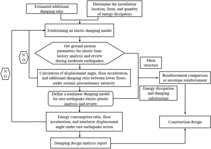
Energy dissipation technology strengthening design process.

Response spectrum curves with different damping ratios.
The arrangement of the vibration reduction device
BRB is a simple, stable and widely used device that reduces the amplitude of seismic response through hysteretic energy dissipation. Mainly composed of internal core plates, external constraint sleeves, and unbonded materials, which can provide additional stiffness and damping for the structure. BRB core plates are usually composed of yield section, transition section, and elastic section, and the division area is shown in Fig. 5. The yield section is the core working unit of the core plate, which dissipates yield energy under axial tensile and compressive loads; The transition section is the connection and transition area between the yield section and the elastic section. To ensure that the end is in an elastic working state, it is necessary to smoothly transition and increase the cross-sectional area of the core plate to avoid stress concentration; The elastic section is located at the end of the core plate, and its main function is to ensure stable connection with the frame beam column node area. Its connection methods include welding, bolt connection, and pin shaft connection40. During the design process, the required yield bearing force and stiffness are mainly achieved by adjusting the proportion of the area and length of each section.
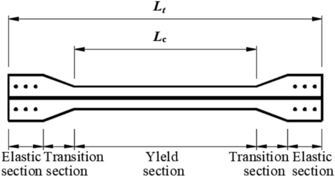
BRB core unit construction.
The selection and arrangement of vibration reduction devices
The Buckling-restrained brace (BRB) can provide stiffness for the structure. Through the calculation by the YJK software, the parameters and quantity of the energy dissipation and vibration reduction devices are determined, as shown in Table 1.
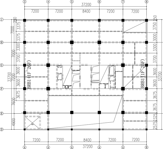
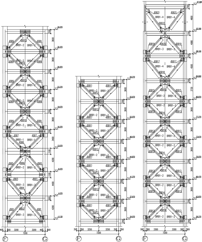
According to the calculation results of the YJK software, when arranging the Buckling-restrained braces, it is known that the structural requirements for seismic reduction in the X-direction have been met. To avoid waste, BRBs were not arranged in the X-direction. Since the stiffness in the Y-direction was insufficient and the displacement was too large, BRBs were arranged in the Y-direction. As arranging one bay could meet the requirements, they were placed in the middle bay of the Y-direction. When arranging the BRBs in the Y-direction of the structure, the principles of “even distribution, dispersion, and symmetry” were followed. The arrangement positions are shown in Fig. 6.
BRB layout details
Comprehensive consideration should be given to factors such as the on-site layout, lifting capacity, and installation conditions. In combination with different structural components such as reinforced concrete and steel structures, determine the size of embedded parts and connection plates, the joint forms of different components, and the embedding methods. The elevation layout of BRB is shown in Fig. 7. The connection details between BRB and existing structural components are shown in Figs. 8 and 9. At the concrete beam-column joints, a bolt-connection method is adopted. At the concrete beam-column steel-encased joints, there are 14 M20 8.8-grade chemical anchor bolts (with an anchorage depth of ≥ 175) and 12 M20 through-bolts. At the steel-encased joints in the concrete beams, 36 M20 through-bolts are arranged. During the installation of relevant components, ensure a firm connection to guarantee the reliable connection between BRB and the concrete structure, so as to meet the structural stress performance.
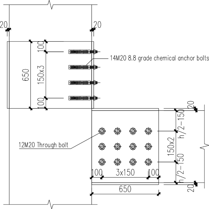
Detailed view of the steel-encased joint at the concrete beam-column connection.
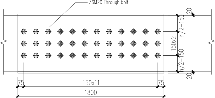
Detail of the steel-encased joint within the concrete beam.
Strengthening model establishment
The structure was strengthened by using energy dissipation and vibration reduction technology, and buckling-restrained braces were set in the middle span in the Y direction. The model after strengthening is shown in Fig. 10.

Reinforced model. Create software: YJK4.1.1, https://www.yjk.cn/.
Design results
Compare and analyze the reinforced model with the renovated model, and the results are shown in Fig. 11 and Tables 2, 3 and 4.

After comprehensively considering several solutions in terms of the impact on the original structure’s architectural functions, economic efficiency, and construction period, the Buckling-restrained brace strengthened structure was adopted. This approach has no impact on the building space and significantly reduces the economic cost. In terms of seismic performance, after the BRB is installed, the first few natural vibration periods of the structure are all reduced, and the maximum inter-story drift ratio is also reduced to meet the requirements of the Technical Specification for Concrete Structures of Tall Buildings in China. Moreover, the strengthened structure reduces the material usage to a certain extent.
link


