
Structural Engineering and Embodied Carbon

As structural engineers, our work involves immersing ourselves in the vision of our clients and producing that vision as purely as possible. Naturally, our work to support an architectural vision must adhere to building standards. Each decision we make also carries an implication for the people building the project and, of course, those paying for it.
In the past decade, a fifth consideration has emerged: reducing the embodied carbon of the structures we design. The cement and steel industries contribute between 15 and 20 percent of global annual CO2 emissions, so this newer motive is quickly becoming one of our most important. For this reason, Blackwell has signed on to the Structural Engineering Institute’s SE2050 initiative, working toward net zero embodied carbon structures by 2050.
Our team of 60 now works to five primary imperatives that we call the 5 Cs: client, code, constructability, cost and carbon. Some projects feature “free wins,” where we can advance toward one or more motives without sacrificing progress toward any others. The simplest example is in avoiding overdesign: less material means lower cost and lower carbon. Our pursuit of lower embodied carbon can also present free wins in how we specify concrete, steel and timber. Other, more impactful decisions—usually involving the choice and layout of the structural system—are not without impact to our client’s vision and must be coordinated across the project team.
Before moving any further, let’s work through the jargon. The goal of all of this is to reduce the global warming potential (GWP), or embodied carbon, of our structures, measured by kilograms of carbon dioxide equivalents (kgCO₂e). A project contributes to atmospheric CO₂ throughout its entire life, from extracting the materials used to build it, to transporting the equipment to the job site, to the continual use of the building’s systems, through demolition and recycling. Here are the ISO-standardized names for these stages of a building’s life:
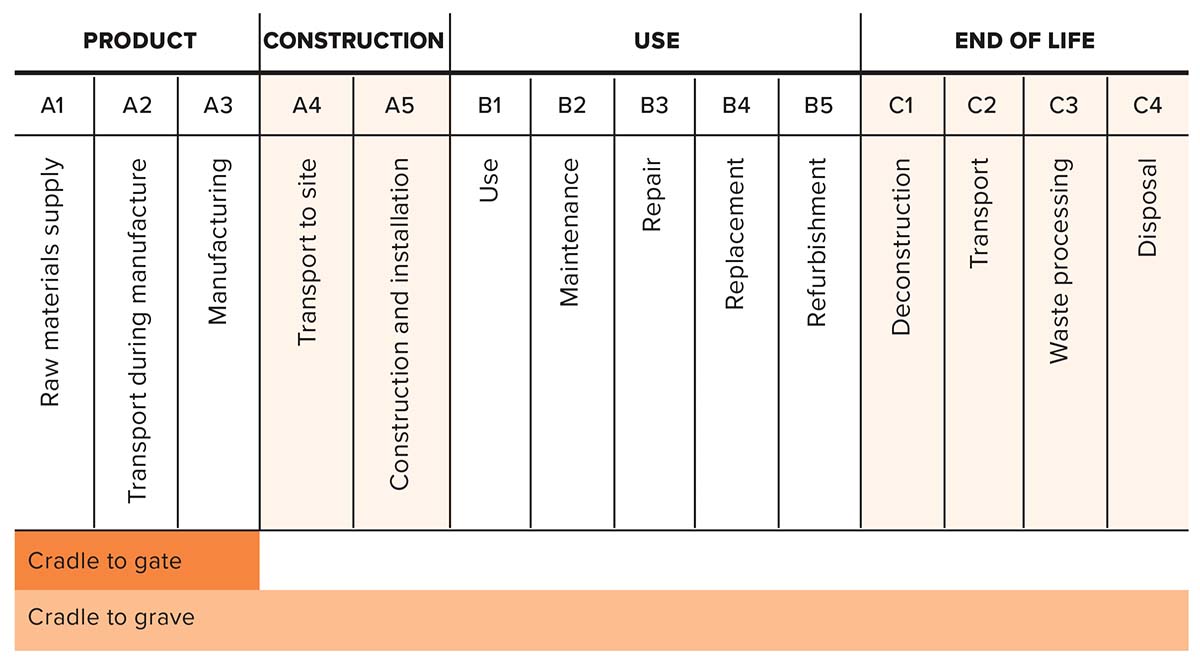
Our focus during structural design is to minimize embodied carbon from “cradle to gate,” that is, from resource extraction to manufacturing of the building components (stages A1–A3). Critically, this means transport to site, and any emissions following, are typically not included in our analysis. This scope allows projects to be compared “apples to apples” without skewed data from proximity to manufacturing.
The GWP of a particular building material is assessed through the use of an environmental product declaration (EPD), a standardized document stating the embodied carbon for a particular material. For standardized documents, there sure is a lot of variance: the kilograms of carbon dioxide equivalents (kgCO₂e) are provided for a material, but there are different unit bases and different levels of specificity and verification. The gold standard is a type III, product-specific, third-party-verified EPD. However it’s easy to be tricked: there are type III, product-specific, internally verified EPDs, as well as type III industry-wide EPDs, neither of which provides the same reliability. Even further, there are type II EPDs, which have no verification requirement at all.
MATERIALS
Blackwell’s practice has long included projects with low-carbon building materials such as mass timber, light wood, straw bale and rammed earth. While it can be gratifying to focus on these projects, they represent a small fraction of the construction market. Carbon-dense materials such as steel and concrete are of primary importance now and for the foreseeable future. We optimize our use of these materials by pursuing three paths to carbon efficiency: design optimization, specification improvements and material innovation.
Path 1: Design optimization
Reductions in embodied carbon can be realized by simply using less. That relationship is linear. The most effective design improvements are high-level, focused on controlling the overall demand on the structure in terms of defining direct load paths, managing geometry and span, and minimizing construction deep below ground or within the water table. These choices belong to the broader client and design team. Alternative options can be investigated and evaluated using the twin currencies of cost and carbon.
At the desk level, our engineers focus on design optimization and refining material selection. Optimization, as a process, is at the core of the practice of structural engineering. Cost and sustainability are linked in important and obvious ways: materially efficient systems are lower-carbon systems; simple systems are typically lower cost.
Path 2: Specification refinement
Blackwell defines embodied carbon limits for structural materials in our contract documents. For designers to effectively specify these limits, and for builders to execute, there must first be an understanding of the benchmark values of embodied carbon in materials, allowing us to specify improvements. Some parts of the industry—for instance, certain suppliers in the concrete and steel sectors—have made great progress in documenting and reducing the embodied carbon of their products, while others lag. Regardless, we believe that these specifications, at minimum, will start conversations and signal to the industry that providing a lower-carbon product is desirable. This effort can progress much more quickly if the design community presents a united front on these limits. We continue to work collaboratively and learn from the industry on how factors such as location, market availability, time constraints and availability of information play a role in meeting these limits.
Path 3: Material innovation
With numerous advancements in material science, it’s easy to get excited about new technologies and find ourselves looking to a particular solution as if it might be “the one.” Through a more critical lens, it’s apparent that as yet there is no one magic solution to the carbon crisis. Instead, we expect greater success from taking advantage of each applicable technology and its compounding marginal benefits.
CONCRETE
Concrete matters most.
Concrete matters most. As architects and engineers work to reduce the embodied carbon in structures, it is tempting to focus on mass timber, renewable materials and carbon sequestration. Doing that won’t solve the problem. This is intended to be provocative, but it’s important not to become distracted. It is a matter of fact that concrete is the second-most consumed product on the planet (after water), and it appears it will remain so. Concrete is prominent in most every building, regardless of whether the primary framing is timber or steel. There are good reasons for this: it is economical, accessible and durable. It is very useful stuff.
U.S. building sector data demonstrates that concrete eclipses both steel and timber in terms of CO₂e emissions. To achieve meaningful reductions in carbon emissions related to structure, industry will need to focus on improving the carbon efficiency of concrete.
Path 1: Design optimization
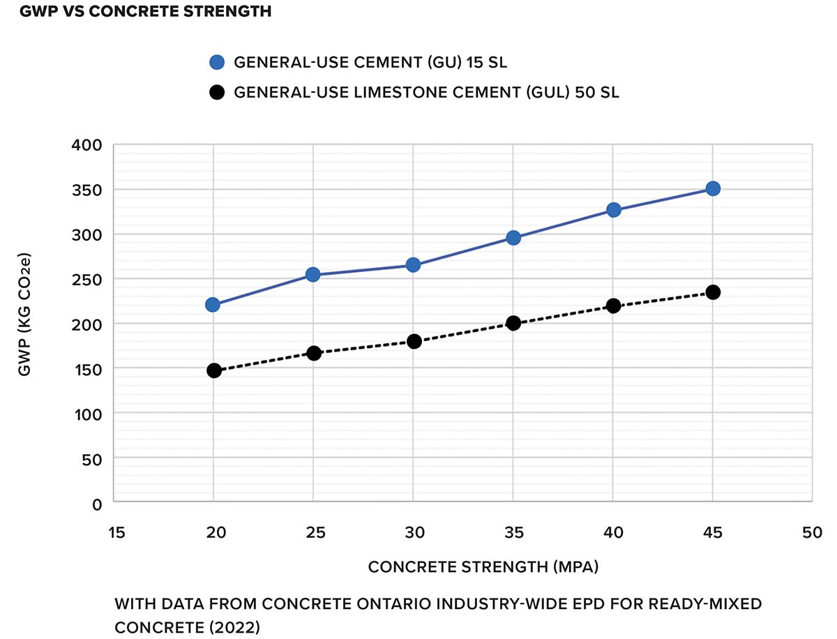
Concrete design optimization should start with an assessment of the required concrete strength. Concrete is a mixture of aggregate, water and Portland cement. The amount of Portland cement present is directly related to concrete’s strength, but is also responsible for its high carbon intensity. The relationship is broadly linear: with increased concrete strength, we see increased carbon intensity. This understanding drives many of our design decisions.
In general, decisions related to concrete geometry will have an impact on the amount of reinforcement present, which also plays a significant role in the GWP of a reinforced concrete element.
Knowing this, we use the following design strategies:
1 Design with low-strength concrete in mind. This means reserving more depth in schematic design for highly stressed elements such as slabs and beams.
2 Be conscious of rebar. In general, decisions related to concrete geometry will have an impact on the amount of reinforcement present, which adds to the material’s carbon intensity. Deeper and voided members require less reinforcement than shallower, solid sections; they can also allow for the use of lower-strength concrete.
3 Lower the specified strength for lightly stressed foundation wall elements and slabs on grade.
4 For framed slabs, consider void forming options such as BubbleDeck or Sonovoid. These systems displace concrete in areas of low stress, reducing the volume and mass of concrete along with the required rebar.
5 For long-span conditions, consider using post-tensioning to refine concrete volume.
6 Avoid mass concrete construction where other options are viable.
Path 2: Specification refinement
The ready-mix concrete industry has made real progress in developing and bringing to market a range of concrete products with reduced carbon intensity relative to benchmarks. Refining and updating our contract specifications can take advantage of—and incentivize—this progress. Concrete Ontario has published an industry-wide EPD that can be used to establish GWP benchmark values for each concrete mix, and to establish project-specific targets for embodied carbon relative to this benchmark. In consultation with the owner and broader design team, we can require concrete mixes that outperform the GWP benchmark by a given percentage. In all cases, we require type III EPDs to verify the GWP of concrete mixes.
The factors that influence GWP are:
1 Concrete strength. GWP increases with strength in a broadly linear way.
2 Use of general-use limestone cement (GUL) versus general-use cement (GU). GUL directly reduces embodied carbon at no additional cost by incorporating high-quality limestone and reducing clinker content. The result is a cement with nearly identical finishing and strength characteristics, but a reduction in CO₂ emissions of about 6 to 8 percent—an easy win.
3 Air entrainment. GWP is increased linearly with air entrainment for a given concrete strength. Added air is an important durability provision in freeze-thaw conditions. Engineers need to determine where it is required and eliminate it where it is not needed.
4 Use of supplementary cementitious materials (SCMs). The production of Portland cement accounts for about 90 percent of the embodied carbon in concrete. SCMs can directly replace a portion of the required Portland cement in concrete. In our market, SCMs are dominated by slag, a postindustrial waste product from steel manufacturing. Replacement of 15 to 25 percent is common. In some applications, replacement ratios of up to 50 percent are possible.
5 Days to design strength requirements. SCMs develop strength more slowly than Portland cement. Increasing required time to design strength from the standard 28 days to 56 days allows for a reduction in Portland cement in favour of SCMs, without use of accelerators.
We expect that normal specification refinements can reduce embodied carbon by 10-15 percent relative to the baseline. The cost implications should be modest—approximately a 2 percent increase in concrete supply cost, or about a 0.5 percent increase in the total cost of placed reinforced concrete, relative to our previous practice. We see these improvements as one of the most prevalent “free wins” on our projects. Finally, note that paths 1 and 2 are cumulative: the refinements of path 2 are applied to the reduced volumes of concrete achieved via path 1.
Path 3: Material innovation
Technology and incentives are combining to spur exciting advances in the cement industry. Low-carbon cement initiatives include research on belitic clinker, calcium sulfoaluminate cements, calcinated clay, carbonated calcium silicate concrete and alkali-activated binders.
MIT research has spun off a cement production company called Sublime Systems that achieves an approximately 40 percent reduction in the GWP associated with the production of conventional cement. It uses electrolysis to develop cement at an ambient temperature of 100°C rather than the 1,450°C required in conventional production, eliminating the kiln and related fossil fuel consumption. Further and critically, the process uses readily available feedstock that may exclude limestone. This feedstock consists of abundant rocks and minerals and can include industrial byproducts such as slag, coal, and ashes. A critical step in the chemistry of the production of Portland cement is the calcination of limestone: CaCO3 + heat —> CaO + CO₂. This reaction is responsible for the majority of CO₂ released in the manufacture of concrete. With slag as a feedstock, Sublime Systems’ chemistry can eliminate limestone and avoid that stream of CO2 production. This represents an extraordinary improvement in the carbon efficiency of cement.
Blue Planet is marketing synthetic limestone (CaCo3) aggregate that sequesters carbon at a rate of 440 kg/mt. The aggregate is fabricated from post-industrial waste CO₂ and recycled concrete or other sources of calcium.
Combining these technologies should enable the production of true zero-carbon concrete—or potentially net negative-carbon concrete. The challenge will be to develop these industries at scale—feedstocks are a limiting factor for Sublime Systems, for instance—and to produce adequate renewable electricity to power their development, as the GWP of cement production varies based on fuel source.
 STRUCTURAL STEEL
Eat less steak.
The manufacture and fabrication of structural steel is carbon intensive. The GWP of steel varies greatly depending on the material source, the production process and the energy source for that production. Not all steel is made equal. Understanding this, we try to “eat less steak” in general—reducing our use of steel overall as we are conscious of its high GWP. Where we do use steel, we focus on developing efficient, elegant systems.
Path 1: Design optimization
The most effective strategy for developing carbon-efficient steel structures is to simply use less steel. To decarbonize our designs, we keep the following in mind:
1 Carefully examine steel sections in a project, prioritizing high utilization and being mindful of detailing.
2 Use secondary bracing to manage stability.
3 Consider composite design with concrete or timber for floor structures.
4 Prioritize direct-load paths; communicate their advantages with clients in the dual currencies of dollars and carbon.
5 Reserve structural depth in schematic design, using open sections (trusses) wherever appropriate. Be willing to coordinate mechanical services to maintain density and avoid increasing floor-to-floor heights and their associated costs.
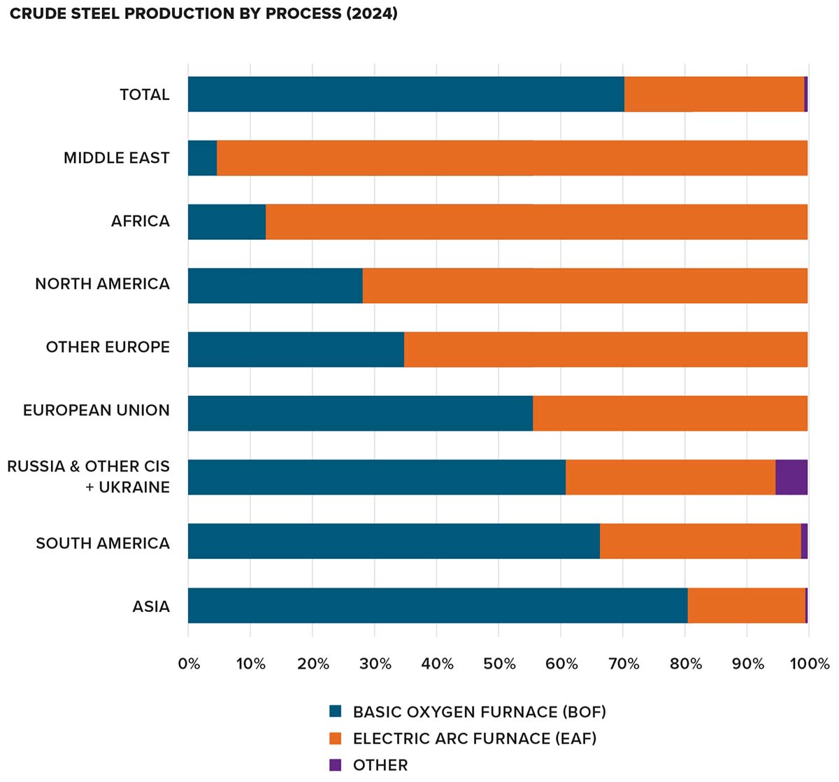
6 Use hollow structural sections (HSSs) judiciously. Generally manufactured using basic oxygen furnaces (BOF), HSS are about 30 percent more expensive—and up to 60 percent more carbon intensive—than EAF (electric arc furnace) structural sections.
Path 2: Specification refinement
There are two primary steel manufacturing processes: basic oxygen furnace (BOF) and electric arc furnace (EAF). Both processes use recycled scrap material, but in different quantities. BOF processes can use up to 20 percent scrap; EAF uses 95 to 97 percent recycled materials. The shortfall of material in BOF processes is made up with iron ore, melted coal (coke) and limestone; thus, BOF production relies heavily on primary resource extraction from mining. Though numbers vary significantly between facilities, EAF steel commonly has GWP impacts that are less than half those of BOF steel.
Currently, both methods of steelmaking are used globally, with about 28 percent attributed to EAF steel and 71 percent attributed to BOF steel. However, the North American market has access to significant amounts of scrap steel, which led to an early investment in EAF manufacturing in the U.S. We now see about 70 percent of steelmaking in the U.S. produced using EAF processes, with similar trends following in Canada. Two of Canada’s three large BOF mills are retiring their BOF furnaces and making the switch to EAF.
Implementing GWP requirements is more nuanced with steel, since the market is not practised working under embodied carbon constraints. Our specifications generally aim to remove BOF steel from being used
on our projects. With the prevalence of EAF steel in North America, this has not had significant cost impacts. The approach may ramp up depending on a project’s emphasis on sustainability. On projects with a strong carbon mandate, we may consider setting targets that reflect ArcelorMittal XCarb and other ultra-low-carbon steel from Europe and Asia. These are the lowest-GWP materials that we are aware of, and these targets restrict the market significantly.
Here are the base requirements that we include in our specifications:
1 The specifications require type III EPDs to be submitted. Using industry averages (type II EPDs) allows BOF steel and EAF steel fabricated from a carbon-intensive power grid to enter the project without accountability.
2 The contract documents specify maximum GWP targets for steel sections, based on their production type (hot-rolled, HSS, OWSJ, metal deck or plate steel). Limits are set such that at least three suppliers can be identified that are at or below the proposed GWP targets.
3 These provisions apply to a minimum of 85 percent of the steel on our projects, on a per tonne basis. This allows the contractor some wiggle room should there be procurement issues.
Path 3: Material innovation
Innovation in structural steel is focused on decarbonizing the manufacturing process.
Direct reduced iron (DRI) is an existing process that uses natural gas to reduce iron ore into iron pellets that can then be used in EAF mills. There is a push to replace the natural gas in this process with hydrogen, which provides an encouraging prospect for green steel in the future.
Promisingly, ArcelorMittal is working to implement industrial-scale use of hydrogen-fuelled DRI in 2025. Their work also includes other decarbonization efforts, such as converting agriculture and forestry waste into fuel, and carbon capture and reuse. ArcelorMittal’s XCarb line employs these technologies, in conjunction with using renewable energy sources, to provide remarkably low-carbon steel products.
TIMBER
Wood is good, but not as good as you think…
Mass timber (glulam, CLT)
The jury is still out on the potential carbon sequestration of wood, as forest management practices are varied—even within certified forests and logging companies. Work is ongoing on this front. The current recommendation from most sources is to tally wood as neutral, rather than carbon-sequestering, in life cycle assessments (LCAs).
In Canada, mass timber comes primarily from domestic manufacturers and from Europe. The major domestic producers are Element5 (Ontario), Kalesnikoff (B.C.), Mercer (B.C.), Nordic (northern Quebec) and Western Archrib (Manitoba and Alberta). All of these manufacturers produce glulam and/or CLT with a GWP of 100–130 kgCO₂e/m3. At this point, we don’t see any of the domestic manufacturers differentiating themselves on embodied carbon, likely due to the already low-GWP nature of the product.
We do not consider A4 (transport of product to the construction site) in our limited LCAs, as this is typically unknown by the design team until after tender. With concrete and steel, because of the carbon intensity of the products and the ubiquity of shops and plants, A4 is a minor contributor to structural embodied carbon. With timber products, the opposite is true: the carbon intensity of the product itself is low, and the plants are potentially distant from the project. Further, while rail transport covers much of the country and is much more carbon-efficient than trucking, we have found that with just-in-time delivery of elements to site, most timber is being trucked from plant to site. Below we have summarized the carbon cost of A4 for a project in Toronto from mass timber producers in various locations.
For the West Coast producers, transportation to Toronto can be equal to—or greater than—the A1-A3 embodied carbon of the product. Surprisingly, European glulam has a lower transport-related GWP than domestically produced West Coast glulam that is shipped by truck to Toronto. The calculation, of course, would differ based on a project’s location.
Unfortunately, there is not enough competition in the local market to require an Ontario-only (or even eastern Canada–only) mass timber fabricator in our specifications for our Toronto projects. We suggest that our clients consider a design-assist process, where carbon accounting is required as part of the RFP—being sure to include A4.
Timber vs. steel
Where there is budget and space to replace steel members with mass timber members, the result will almost always be beneficial in terms of GWP optimization. An efficiently designed timber member will have between 30 to 40 percent of the GWP of a steel member. An exception to this would be replacing open steel sections with glulam beams or joists. If low-carbon steel is used, it may have a lower GWP and cost compared to the timber alternative.
Timber vs. concrete
A timber deck of a similar thickness to a concrete slab will have 30 percent of the GWP—a significant reduction. But this can be complicated by fire rating and the requirement for concrete topping on wood deck, both of which will eat into mass timber’s advantage. In timber’s favour, there may be a decrease in finishing requirements and a reduction in foundation volume when compared with a concrete system. Timber can provide a major advantage over concrete if it enables a conventional shallow foundation system in a structure that would, if constructed from concrete, require deep foundations.
To minimize the embodied carbon of mass timber, we use the following design strategies and specifications:
Path 1: Design optimization
1 Focus on highly utilized sections and hunt for volume, particularly in timber deck. Optimizing the grid layout at the beginning of a project is critical for success.
2 For projects in eastern Canada, design for spruce-pine (SP) glulam, as it is available from local fabricators. Douglas fir-larch glulam has the ability to decrease the volume of timber, but will necessarily have large transportation GWP costs.
3 If a fabricator is selected that offers higher-grade glulam, advocate for a redesign of members to maximize utilization for its stronger material properties. This can reduce cost and GWP.
4 In detailing timber connections, maximize bearing where possible, and minimize steel. Where connections are designated to be designed by the mass timber fabricator, set the expectation of low-steel connections with details showing intent. We use optimized off-the-shelf products wherever possible.
5 For floor structures, consider composite designs between the beams and concrete or timber deck, particularly for vibration design.
6 To achieve a two-hour fire resistance rating over a timber structural member, 91 mm of glulam costs roughly 13 kgCO₂e/m2, while three layers of 5/8” type X gypsum wallboard (GWB) costs roughly 9kgCO₂e/m2. In terms of carbon savings, gypsum wins if the member in question does not have any inherent fire rating as sized for strength. But the larger the member is for strength, the more inherent rating it will have—and engaging its timber char protection properties may result in a lower GWP.
Path 2: Specifications refinement
1 All glulam is to be sourced from North America or Europe.
2 We require type III EPDs to be submitted. The market is small, and timber is already seen as a low-GWP option. We don’t anticipate that this requirement will impact the market, but measurement is part of the process of improving outcomes.
3 We ask for accounting of A4 GWP and a transportation plan to be submitted at tender. Transportation is relatively cheap dollar-wise, and hasn’t been a deterrent in projects to date. Showing that transportation is expensive GWP-wise will help shift the market in favour of producers local to the market, or with low-carbon transportation initiatives.
Path 3: Material innovation
In the wood industry, forestry practices are continuing to progress toward more sustainable harvests, potentially allowing for accurate estimation of full-life-cycle carbon sequestration. As the market expands, costs and transportation-related GWP should continue to decrease relative to other materials. However, investment in the wood industry does not trend toward material innovation. The innovation here is about furthering the adoption of timber in construction, resulting in a decreased reliance on higher-GWP materials such as steel and concrete. As mass timber projects become more common, they will increasingly be de-risked by contractors and designers.
SYSTEM DECISIONS
A deeper understanding of what drives the carbon emissions of different materials allows us to ensure an efficient structural system is used, and to quantify the carbon savings of our design decisions. This process is more effective the earlier it occurs in a project’s timeline.
Blackwell has created a system of schedules within our BIM environment, linked with our repository of GWP values, to track the embodied carbon of structural elements in our work. As a result, there is always a current count of the kgCO₂e present, and we can conduct “either-or” studies through the design phases. We also use this information to back-check third-party life-cycle analyses, similar to our review of costing reports.
Gymnasium framing study
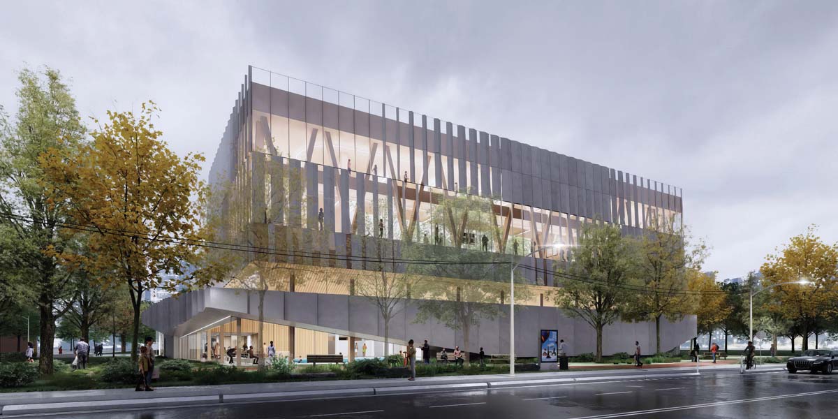
The future John Innes Community Recreation Centre, which we worked on with MJMA for the City of Toronto, includes a lap pool and leisure pool, gymnasiums, fitness space, running track and many community spaces. The recreation program is stacked, with a gym floor above the aquatics hall. This configuration raises challenges in terms of structural capacity and vibration mitigation.
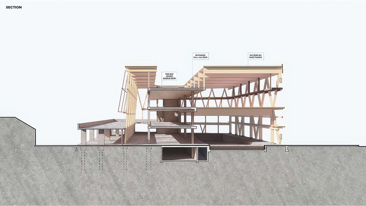
As this project has a sustainability mandate and a total carbon cap under the Toronto Green Standard, the plan was to have a mass timber primary system with CLT floor assemblies supported on glulam beams. As the design developed, however, the required depth of the glulam beams began to encroach on the ceiling height of the aquatics hall. Space for integrating mechanical services was also limited, as providing openings in mass timber is restricted from a fire-protection and shear-capacity perspective. Ultimately, vibration criteria governed the design, and the depth constraints proved to be untenable. An alternative design employing a hybrid system of CLT slabs bearing on custom trusses fabricated from ultra-low-GWP steel was compared to the initial glulam scheme in terms of embodied carbon and cost.
The truss substitution resulted in a system that was able to meet vibration criteria at a cost of just 45 percent of the glulam girders. Employing X-Carb steel sections, the embodied carbon was reduced to approximately 75 percent of the timber alternate. If conventional EAF steel is used, the expected cost is 35 percent of the glulam, but the embodied carbon is 200 percent of the mass timber option.
Specifying low-GWP steel in this application is a clear win, highlighting the importance of evaluating structural systems based on their specific application. In our effort to lower embodied carbon, we’ve learned that direct material-to-material comparisons cannot paint a full picture. Instead, we need to consider the entire system. Efficiency is often found in hybrid solutions, where materials are applied appropriately based on their strengths.
Concrete slab vs. mass timber
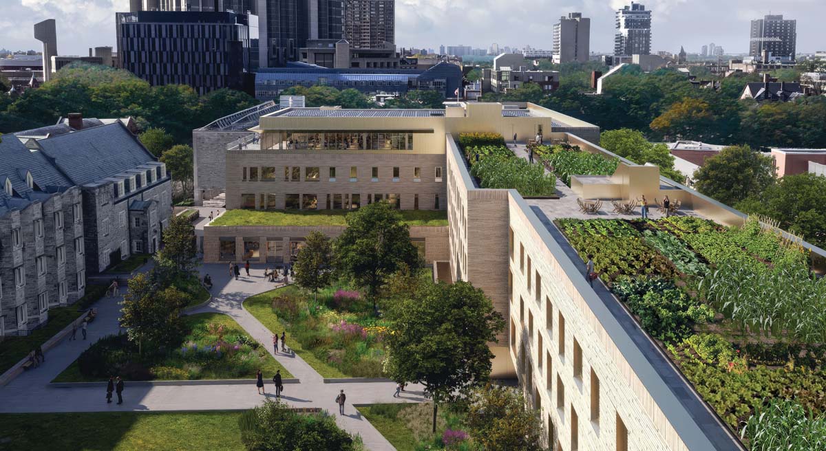
Our project for the University of Toronto’s future Trinity College Lawson Centre for Sustainability, designed with Mecanoo in partnership with RDHA, included a mandate for a low-embodied-carbon structure. The above-grade scheme used CLT floor and roof decks. These were supported on CLT walls where exposed, light-gauge steel stud walls where concealed, and concrete walls at the circulation cores. Glulam beams and columns were used in the academic wing. The system offered substantial structural carbon savings, with the structure coming in at 115 kgCO₂e/m2—compared to the Carbon Leadership Forum benchmark of 400 kgCO₂e/m2.
The Trinity College project also offers an opportunity for a system comparison between a suspended concrete slab and a mass timber floor plate. The ground floor of the building’s academic wing is a concrete slab with the same spans and demands as the mass timber floors above. The mass timber system is substantially deeper than the concrete system—1,200 mm at beams and 670 mm at joists, compared to 350 mm at drops and 250 mm at the flat plate slab. However, the timber system is designed to allow mechanical systems to run within the structural depth. The timber system has just 32 percent of the embodied carbon of the concrete system.
CONCLUSION
We at Blackwell have been lucky to participate in the innovation of Canada’s building design community, and we consider reducing embodied carbon to be a new frontier. This innovation is best imagined as two-ended: the front end includes strategy, design and theory; the tail end is implementation in built projects. In a warming world, the stakes are high: how do we ensure that this innovation keeps an appreciable pace and that we maximize its impact?
We believe that our community’s approach to reducing embodied carbon should be similarly two-ended: we think of these efforts as working together and working united.
From our experience, the greatest outcomes come from positive scheme and system decisions, and these can only be achieved through the design team working together. More broadly, innovation will move faster if we share information freely: we aim to contribute to forums on carbon-centric design and are committed to sharing our research with anyone who asks. Our design community can achieve much if we all have a similar approach.
You can imagine there will be resistance to the kinds of design and specifications recommendations we are making. Not every decision is cost-neutral or difficulty-neutral, and ultimately, each proposal will be compared with the lowest common denominator. If we want to ensure our efforts are implemented in built projects, we must work united: our industry must aim to make environmental product declarations and GWP limits the norm, rather than the exception.
By working together and working united, we can make an industry-wide impact. For an industry as emissive as ours, this means a global impact. Wherever you can contribute, we hope you will join us in these efforts.
Ian Mountfort is a principal at Blackwell, and leads Blackwell’s carbon research group with Simon Rayment, Jordan Schneider and Skylar Mason.
link


