Structural behaviour of built-up I-shaped CFS columns

This study employs finite element analysis to determine the critical elastic buckling loads (local, distortional, and global) for all column configurations. Subsequently, established design codes (AISI S100 and AS/NZS 4600) are utilized, with Eqs. (2) to (12), to convert the critical elastic loads into their corresponding nominal counterparts. Finally, Eq. (13) is applied to ascertain the overall elastic nominal buckling load for each type of built-up column, where single c-sections are not connected with screws. Detailed results are presented in Table 4.
When built-up back-to-back C-sections, comprising large webs and flanges, are assembled by screwing them together in a single line, the Pcrl increases significantly, accompanied by increments in Pcrd, Pcre, and Pn. However, when employing two lines of screws for connection and subsequently reducing the screw spacing, Pcrl experiences a substantial surge, while Pcrd sees a pronounced increase, along with enhancements in Pcre and Pn.
Changes in the thickness of these members, exemplified by (2*C200*75*20*t), lead to variations in load-carrying capacity without altering the buckling type. Similarly, modifications in screw spacing do not influence the buckling type but exert a notable impact on load-carrying capacity, as depicted in Tables 5, 6 and 7.
For instance, when considering (2*C200*75*20*1.5) with zero screws, the Nominal Axial Strength is measured at 124 kN. However, augmenting the thickness of the built-up section by 33.33% and 66.67% correspondingly increases the Nominal Axial Strength by 63.71% and 137.1%, respectively, as outlined in Table 4.
When built-up back-to-back c-Sect. (2*C150*B*20*2) which is screwed together, there is a discernible impact on structural behavior. Initially, when it is screwed together with one line of screws, then by reducing screw spacing, Pcrl increases significantly along with notable increases in Pcrd, Pcre, and Pn. Moreover, upon employing two lines of screws to connect C-sections, reducing the screw spacing exhibits a profound effect: it substantially elevates Pcrl, markedly augments Pcrd, and boosts Pcre and Pn. These alterations in screw configurations underscore the critical role of fastening mechanisms in load distribution and structural integrity.
Additionally, changes in the flange width of these members (2*C150*B*20*2) provoke notable variations in load carrying capacity and buckling behavior. Likewise, modifications in screw spacing exert a tangible influence on buckling characteristics and load-carrying capacity. This interplay of factors is elucidated in Tables 8, 9 and 10, providing a comprehensive understanding of how design parameters affect structural performance.
Transitioning to the specific case of (2*C150*50*20*2), the absence of screws yields a Nominal Axial Strength of 116 kN. However, as the flange width of this built-up section increases by 30% and 50% respectively, the Nominal Axial Strength experiences substantial increments of 61.21% and 93.1% correspondingly. For detailed insights, refer to Table 4, which highlights the direct correlation between flange width adjustments and axial strength enhancement.
When built-up back-to-back c-Sect. (2*CD*75*20*2) are screwed together, the arrangement significantly impacts the structural integrity. Initially, when connected with a single line of screws, a reduction in screw spacing results in a notable increase in Pcrl, thereby affecting Pcrd, Pcre, and Pn. Moreover, employing two lines of screws for connection intensifies this effect, particularly augmenting Pcrl and Pcrd, followed by subsequent increases in Pcre and Pn.
Alterations in the web depth of these members (2*CD*75*20*2) invariably alter their load-carrying capacity. Furthermore, adjustments in screw spacing influence the buckling behavior, especially noticeable when utilizing smaller screw spacings as exemplified in (2*C100*75*20*2). These variations are elucidated in detail within Tables 6, 8 and 11.
In scenarios where (2*CD*75*20*2) is employed and the screw count reaches zero, the Nominal Axial Strength amounts to 244 kN. However, as the web depth of the built-up section increases by 50% and 100%, the Nominal Axial Strength experiences a respective decrease of 8.2% and 16.8%, as outlined in Table 4.
In terms of results, a notable enhancement in nominal axial strength (Pn) is observed. Specifically, for one lane of screws, the increase is 15%, 13%, 11%, 5%, 6%, 6%, and 5% for the corresponding screw spacings mentioned earlier. Conversely, for the configuration with two lanes of screws, Pn experiences increases of 15%, 14%, 12%, 8%, 8%, 8%, and 7%, respectively. See Table 12.
For economic reasons, it is advisable to avoid the utilization of Lcrl/4 and Lcrl/3 screw spacings. The rationale behind this recommendation is that these configurations necessitate a substantial number of screws, resulting in closely spaced screws. Consequently, steering clear of these two spacing types is deemed optimal.
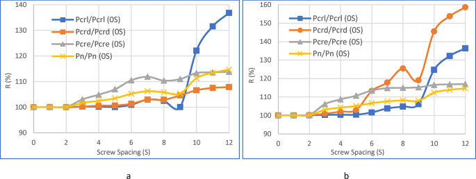
As depicted in Fig. 8b, employing a single lane of screws along the centerline of the webs can significantly enhance the critical elastic local buckling load (Pcrl). This enhancement is particularly noteworthy when the spacing is equal to Lcrl/n, where n takes values of 1, 2, 3, and 4. With each incremental value of n, there is a notable surge in Pcrl, accompanied by a marginal increase in Pn.
Referencing in Fig. 8a, an alternative approach involves employing two lanes of screws, leading to an improvement in the critical elastic distortional buckling strength (Pcrd). This improvement is especially pronounced when the spacing equals Lcrl/n, with n ranging from 1 to 4. Notably, as n increases, there is a substantial rise in (Pcrd) and a gradual uptick in (Pn).
For economic considerations, it is recommended to opt for a single lane of screws and adopt a screw spacing equal to S10 or Lcrl/2. This configuration results in significant increases across critical elastic local buckling load (Pcrl), critical elastic distortional buckling strength (Pcrd), critical elastic distortional-torsional buckling strength (Pcre), and Pn. Specifically, there is a remarkable increase of 22%, 7%, 13%, and 11%, respectively.
Screw spacing, denoted as ‘Si,’ is characterized by the interval when ‘i’ ranges from 0 to 12. Additionally, Lcr/n is defined for ‘n’ values spanning from 1 to 4.
Referring to Fig. 9a and b, when the value is 0, it corresponds to ‘S0,’ indicating that no screws are utilized. The subsequent values, 1 through 4 on the graph, represent ‘S1,’ ‘S2,’ ‘S3,’ and ‘S4,’ corresponding to Lcre/1, Lcre/2, Lcre/3, and Lcre/4, respectively.

Examining the correlation between column load and screw spacing, considering both critical and nominal loads.
Similarly, values 5 through 8 on the graph, namely 5, 6, 7, and 8, correspond to ‘S5,’ ‘S6,’ ‘S7,’ and ‘S8,’ aligning with Lcrd/1, Lcrd/2, Lcrd/3, and Lcrd/4, respectively. Furthermore, values 9 through 12 on the graph, specifically 9, 10, 11, and 12, correspond to ‘S9,’ ‘S10,’ ‘S11,’ and ‘S12,’ representing Lcrl/1, Lcrl/2, Lcrl/3, and Lcrl/4, respectively.
link


