Design of displacement-based viscous damper damping structures
A massive galvanic fluid damper with many electrodes operating in shear mode was regulated the vibration suppression capabilities of smart fluid materials such as magnetorheological and galvanic41. It was discovered that the megacurrent variable-fluid damper greatly reduced vibration, with a 91.03% damping effect and a 43.8% adjustable range39.
Displacement-based resilience modeling of viscous damper and design of seismic-damped structures
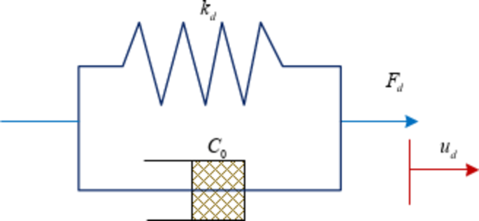
The performance of VD, which is the fundamental component of VD design, is primarily described by the RF model42. An appropriate RF model can achieve the best simulation effect, so as to accurately analyze the performance of the VD. Common RF models for VD include linear model, linear Kelvin model, linear VD (Maxwell) model, and Wiechert model. In the numerical simulation of VD, the Kelvin model and Maxwell model are usually used43. The Maxwell model, on the other hand, consists of an elastic element and a viscous element in series and is more suitable for simulating viscous fluid dampers44. Therefore, in order to more comprehensively analyze the performance of VD under various operating conditions, the study utilizes the Kelvin model in combination with the Maxwell model as the RF model of VD for simulation respectively. The Kelvin model is shown in Fig. 1.

In Fig. 1, \({F_d}\) denotes the RF provided by the VD. \({k_d}\) denotes the stiffness coefficient. \({u_d}\) and \({\dot {u}_d}\) denote the relative deformation (RD) of the two ends of the VD. \({c_d}\)denotes the damping coefficient (DC). When the Kelvin model is set to zero stiffness, the model degenerates into a viscous unit that simulates the effect of the storage stiffness of the VD on the damping produced by the linear VD36. The mathematical expression for the RF of the Kelvin model is shown in Eq. (1).
$${F_d}={k_d}{u_d}+{c_d}{\dot {u}_d}={F_0}\sin \left( {\omega t+\varphi } \right)$$
(1)
As shown in Eq. (1), this RF simulates the RF provided by the VD under sinusoidal loading. \({F_0}\) denotes the maximum outward force of the VD. \(\varphi\)denotes the phase difference between the displacement and the VD. The linear behavior of the VD under small-amplitude vibration can be accurately described in the Kelvin model, and its damping characteristics are more stable. The Kelvin model is suitable for simulating the characteristics of viscoelastic dampers and is an effective tool for designing and optimizing VD. Moreover, Maxwell model is commonly used to simulate VD, whose structure mainly consists of cylinder, piston rod, pin head and piston45. Maxwell model is shown in Fig. 2.
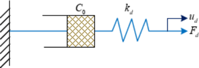
The Maxwell model fits the nonlinear behavior of VD with nonlinear boundary characteristics, as displayed in Fig. 246. Its damper output force is proportional to the RD of the ends, while the elastic unit output force is inversely proportional to the RD of the ends. This model focuses more on the frequency dependence of the VD and is more suitable for simulating the response behavior of BSs at higher amplitudes, higher frequencies and with less damping. The mathematical expression for the RF of the Maxwell model is shown in Eq. (2).
$${F_d}={C_0}{\dot {u}_d}$$
(2)
In Eq. (2), \({C_0}\) denotes the DC in the case of zero frequency. Conventional SD of BSs tends to cause large losses to the structure, including renovation losses and equipment losses. Therefore, in order to minimize these losses, displacement-based VD damping structures are designed by investigating the location-based adjustment of equipment to improve the SP of BSs. In this design, the study considers the VD in a BS as a single-degree-of-freedom system (SDFS). Moreover, it is given an additional damping ratio (DR) and target displacement (TD) at a set level. The response spectrum of this damper’s displacement in the vibrating environment is then used to compute the equivalent TD and the matching equivalent period. To ascertain the forces on each building floor during seismic circumstances, the base shear of the structure can then be computed and the shear forces (SF) can be distributed throughout the structure’s floors. Finally, based on the proportion of SFs carried by the VD, the SFs carried by the dampers in each floor of the BS are determined and the appropriate dampers are selected for the adjusted design. The design flow of displacement-based VD damping structures is shown in Fig. 3.
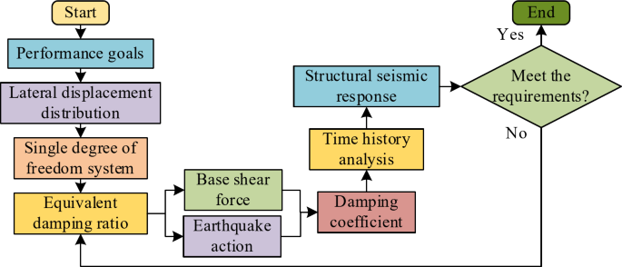
Design flow of displacement-based viscous damper damping structures.
In Fig. 3, in the design process of displacement-based VD damping structures, a suitable performance objective is first determined and the lateral displacement (LD) distribution of the BS is calculated with this objective. At the same time, the nonlinear multi-degree-of-freedom system is equated to a SDFS. After determining the equivalent DRs corresponding to the TDs, the base shear of the BS and the seismic actions at each floor are calculated. At the same time, the DC is calculated based on the additional DR. After that, the dampers are installed in accordance with the determined DCs, and the seismic response of the structure is determined by analyzing the seismic damping effect of the BS over time using the RF model. If the structural seismic response results are unsatisfactory, then return to the TD determination stage to reset the TD. If satisfactory, the process is concluded. Equation (3) shows how the LD distribution curve is calculated.
$$D\left( x \right)=\frac{{{u_H}}}{2}\left( {\frac{{3x}}{H} – \frac{{{x^3}}}{{{H^3}}}} \right)$$
(3)
In Eq. (3), \(D\left( x \right)\) denotes the LD at \(x\).\(H\) denotes the height of the BS. \({u_H}\)denotes the displacement at the apex of the BS. This formula for calculating LDs is only applicable to frame structures that are symmetrical and have a regular arrangement of members, which is quite different from the actual situation47. Therefore, the study is based on the first-order modes of the structure to carry out the formula for calculating the LD applicable to the building steel structure, as shown in Eq. (4).
$${\Delta _i}=\frac{{{\omega _\theta }{\theta _c}{h_i}\left( {4H – {h_i}} \right)}}{{\left( {4H – {h_1}} \right)}}$$
(4)
In Eq. (4), \({\Delta _i}\) is the displacement of the ith floor BS. \({\theta _c}\) denotes the angular limit of interstory displacement. \({\omega _\theta }\) denotes the amplification adjustment factor. \({h_i}\) denotes the height of the ith floor BS from the bottom. The equivalent displacement expression for the SDFS is shown in Eq. (5).
$${\Delta _d}=\frac{{\sum\nolimits_{{i=1}}^{n} {{m_i}\Delta _{i}^{2}} }}{{\sum\nolimits_{{i=1}}^{n} {{m_i}{\Delta _i}} }}$$
(5)
In Eq. (5), \({\Delta _d}\) is the equivalent displacement. \({m_i}\) is the mass of the ith floor BS. The mathematical expression for equivalent height is shown in Eq. (6).
$${\Delta _H}=\frac{{\sum\nolimits_{{i=1}}^{n} {{m_i}\Delta _{i}^{2}{h_i}} }}{{\sum\nolimits_{{i=1}}^{n} {{m_i}{\Delta _i}} }}$$
(6)
In Eq. (6), \({\Delta _H}\) denotes the equivalent height. The mathematical expression for equivalent mass is shown in Eq. (7).
$${\Delta _m}=\frac{{\sum\nolimits_{{i=1}}^{n} {{m_i}{\Delta _i}} }}{{{\Delta _d}}}$$
(7)
In Eq. (7), \({\Delta _m}\)denotes the equivalent mass. The displacement response spectrum is mainly used to describe the maximum displacement response of a SDFS with different intrinsic periods under a given seismic excitation48. The mathematical expression for the displacement response spectrum is shown in Eq. (8).
$${S_d}={\left( {\frac{T}{{2\pi }}} \right)^2}{S_a}={\left( {\frac{T}{{2\pi }}} \right)^2}\alpha g$$
(8)
In Eq. (8), \({S_d}\) denotes the equivalent displacement response spectrum of the SDFS. \({S_d}\) denotes the self-oscillation period of the BS. \({S_a}\) denotes the acceleration response spectrum and \(\alpha\) denotes the seismic influence coefficient. \(g\) denotes the gravitational acceleration.
Design and analysis method of viscous damper damping structure based on multi-objective optimization
After the design of displacement-based VD damping structures, the structural performance of their energy dissipation and damping needs to be evaluated by using time-course analysis (TCA) method and so on. The analysis methods of VD damping structures mainly include time course analysis method and energy analysis method49. TCA analysis is a dynamic analytic technique used primarily to assess and forecast a structure’s response to dynamic loads like earthquakes. It solves a structure’s differential equations of motion through stepwise integration50. Since the seismic damping structure of a building mainly consists of energy dissipating members and main structure, the study decomposes the main body of the model into two sections, energy dissipating members and main structure, in performing the analysis of the seismic damping structure. The structural reaction of the structure at all times can be obtained by applying the time course analysis approach for building performance analysis, allowing for a more thorough evaluation of the structure’s seismic dampening effect and performance51. The dynamic equations for the time course analysis are shown in Eq. (9).
$$\left\{ {{F_{eq}}\left( t \right)} \right\}=\left\{ {{F_I}\left( t \right)} \right\}+\left\{ {{F_D}\left( t \right)} \right\}+\left\{ {{F_S}\left( t \right)} \right\}$$
(9)
In Eq. (9), \(\left\{ \cdot \right\}\) denotes the matrix, \({F_{eq}}\) denotes the elastic-plastic force. \({F_I}\) denotes the inertial force of the mass. \({F_D}\) denotes the damping force and \({F_S}\) denotes the internal force. The mathematical expression for the matrix equilibrium of the BS is shown in Eq. (10).
$$R\left( t \right)=\left\{ M \right\}a\left( t \right)+\left\{ C \right\}v\left( t \right)+\left\{ K \right\}d\left( t \right)+{R_{NL}}\left( t \right)$$
(10)
In Eq. (10), \(R\left( t \right)\) denotes the external load on the BS. \(M\), \(C\), and \(K\) denote mass, proportional damping, and stiffness, respectively. \(d\left( t \right)\), \(v\left( t \right)\), and \(a\left( t \right)\) denote the displacement, velocity, and acceleration at the moment of time node \(t\), respectively. \({R_{NL}}\left( t \right)\)denotes the sum of nonlinear cells. The energy analysis method can take into account the energy changes in the seismic case, and therefore it can well reflect the plastic damage produced by the BS under vibration conditions52. The energy analysis approach model is shown in Fig. 4.
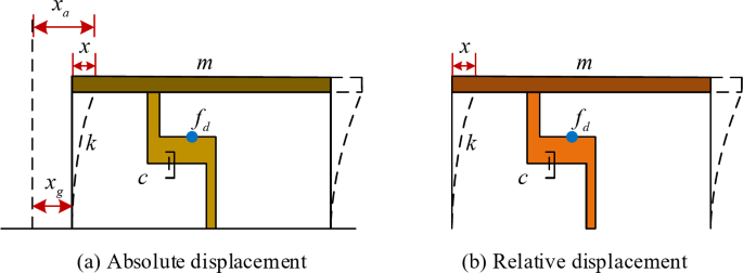
Energy analysis approach model.
As shown in Fig. 4, energy analysis models are generally categorized into absolute and relative displacement53. Absolute displacement analysis focuses on the energy changes of the overall structure, while relative displacement analysis focuses on the energy transfer and consumption among individual members54. Therefore energy analysis models can provide a more comprehensive assessment of the performance and damage of BSs under seismic conditions. The energy analysis model under absolute displacement is shown in Eq. (11).
$$cv^{\prime}\left( t \right)+m\bar {a}\left( t \right)+{f_1}+{f_2}=0$$
(11)
In Eq. (11), \(m\) denotes the mass factor and \(c\) denotes the damping factor. \(v^{\prime}\left( t \right)\) and \(\bar {a}\left( t \right)\) are the velocity and absolute acceleration of the SDFS relative to the ground surface, respectively. \({f_1}\) denotes the RF of the BS and \({f_2}\)denotes the RF of the energy dissipator of the VD55. The energy analysis model under relative displacement is shown in Eq. (12).
$$cv^{\prime}\left( t \right)+ma^{\prime}\left( t \right)+{f_1}+{f_2}= – mg\left( t \right)$$
(12)
In Eq. (12), \(a^{\prime}\left( t \right)\) represents the acceleration of the SDFS relative to the ground surface. The study combines the TCA analysis method with the energy analysis method, which can reflect the response of BSs under earthquakes more comprehensively. The traditional VD arrangement method fails to take into account the DC and energy distribution of the structure under seismic conditions. Therefore, the study optimizes the arrangement of VD. To obtain the optimal damping effect, a suitable objective control function is selected and the dampers are distributed logically. The problem of allocation of multiple dampers belongs to the multi-objective optimization problem. The study comprehensively applies the traditional multi-objective optimization methods such as the constraint method and the weighted coefficient summation method to design a structural design method based on multi-objective optimization for vibration damping of VD, as shown in Fig. 5.
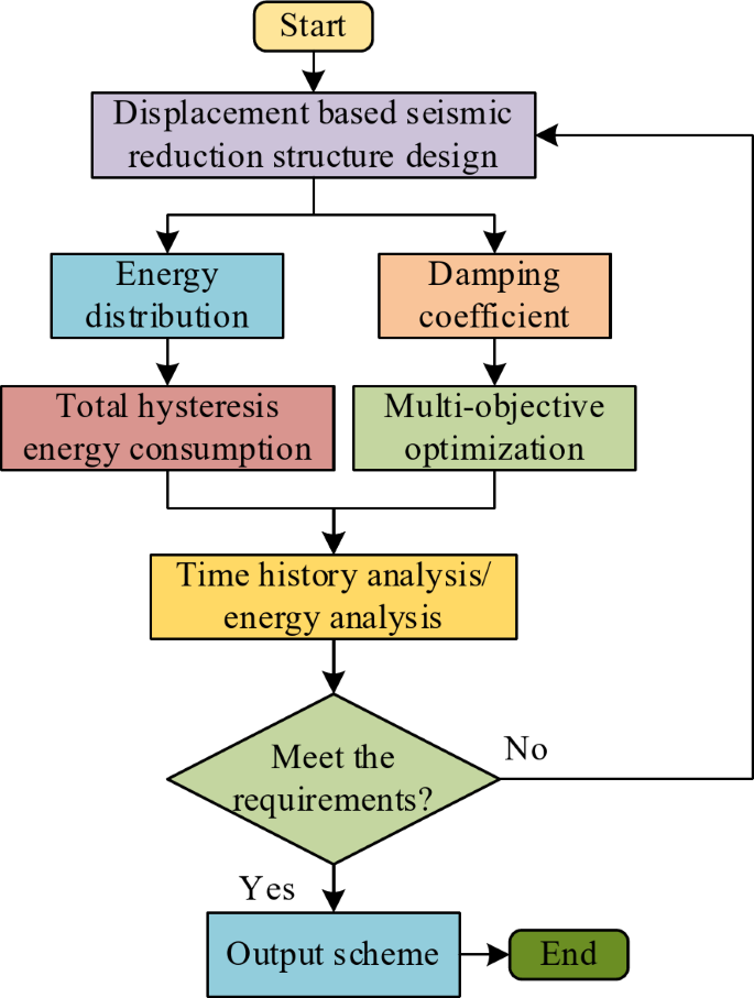
Multi-objective optimization based structural design method for vibration damping of viscous damper.
In Fig. 5, the DC and energy distribution of the structure are considered in the design process of VD damping structure based on multi-objective optimization. Firstly, the DCs are studied and calculated, and the DCs are reasonably distributed using the multi-objective optimization method. Meanwhile, after calculating the energy distribution, the total hysteretic return dissipation of the structure is determined. Finally, the damping performance is evaluated by combining the time course analysis method and energy analysis method. Throughout the process, it is determined whether the performance meets the requirements or not. If it is not satisfied, it is returned to the displacement-based VD damping structures design stage and re-optimized and adjusted. If satisfied, the final damping structure design solution is output. The assignment objective function of the multi-objective optimization method is shown in Eq. (13).
$${n_i}=\frac{{A \times N \times {\theta _i}}}{{\sum\nolimits_{{i=1}}^{n} {{\theta _i}} }}+\frac{{B \times N \times {a_i}}}{{\sum\nolimits_{{i=1}}^{n} {{a_i}} }}+\frac{{C \times N \times {v_i}}}{{\sum\nolimits_{{i=1}}^{n} {{v_i}} }}$$
(13)
In Eq. (13), \({n_i}\) denotes the number of VD arranged at the ith floor of the BS. \(A\), \(B\) and \(C\) all denote weighting factors and satisfy \(A+B+C=1\). \(N\) denotes the total number of VD. \({\theta _i}\) denotes the interstory displacement angle (ISDA) of the ith floor of the structure. \({a_i}\) and \({v_i}\)denote the acceleration and velocity of the ith layer structure, respectively56. The formula for the DC is shown in Eq. (14).
$${C_i}=\frac{{{F_{d,i}}}}{{2\pi {\Delta _{d,i}}}}$$
(14)
In Eq. (14), \({C_i}\) denotes the DC at the ith floor of the BS. \({F_{d,i}}\) denotes the SF on the damper arranged at the ith floor of the BS. \({\Delta _{d,i}}\) denotes the axial displacement of the damper at the \(i\) level of the BS. The formula for the displacement lateral force is shown in Eq. (15).
$${F_i}=\frac{{{V_b} \times {m_i}{\Delta _i}}}{{\sum\nolimits_{{i=1}}^{n} {{m_i}{\Delta _i}} }}$$
(15)
In Eq. (15), \({F_i}\) denotes the equivalent displacement lateral force at the ith floor of the BS. \({m_i}\) denotes the gravity load value at the ith floor. \({V_b}\) denotes the base SF. \({\Delta _i}\) denotes the TD value for the design of the ith floor.
link


